Updated 2008-04-17 to clarify the marked-up screenshot of the Color Matrix view. If you’ve seen this post before, check out the before and after.
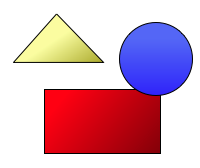
So, let’s say you want to convert an image to a mask.
→

This is easy to do with the Color Matrix filter in Core Image.
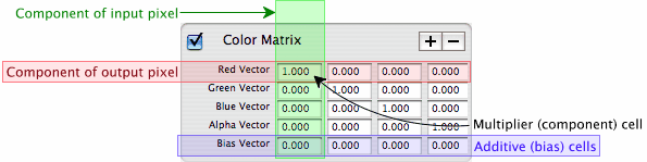
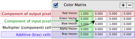
If you’ve ever looked at the Color Matrix filter out of curiosity, you were probably frightened by its imposing array of 20 text fields:
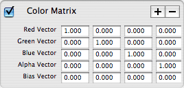
Don’t worry. The fields are actually very simple, though not explained in the UI:
- The Red, Green, Blue, and Alpha rows each represent a component of an output pixel.
- Each column represents a component of an input pixel.
- Each cell in the component rows is a multiplier.
- Each cell in the “Bias vector” row is an addend.
(The documentation for the Color Matrix filter actually does explain it, but I like my explanation better for not using fancy math terms like “dot product”.)
So with this tool, our task is redefined like so:
- Set the three color-component vectors (Red Vector, Green Vector, and Blue Vector) to 0, 0, 0, 1. (In other words, multiply every input color component by 0, and the input alpha by 1, and set all three color components to that.)
- Set the Alpha Vector to 0, 0, 0, 0. (In other words, multiply all input components by 0, and set the output alpha component to that. In other other words, set every output alpha component to 0.)
- Set the Bias Vector also to 0, 0, 0, 1. (In other words, add 0 to all three color components, and add 1 to the alpha component.)
You can generalize this to the extraction of other channels. Let’s say you want to make a mask of the blue channel:
- Set the three color-component vectors to 0, 0, 1, 0. (For every output color component, multiply every color component by 0, except for blue. Multiply blue by 1—i.e., don’t change it.)
- Set the Alpha Vector to 0, 0, 0, 0. (Multiply every alpha component by 0—i.e., set every output alpha component to 0.)
- Set the Bias Vector to 0, 0, 0, 1. (Add 1 to the alpha component. This step is invariant; you always add to the alpha component.)
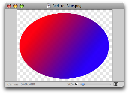
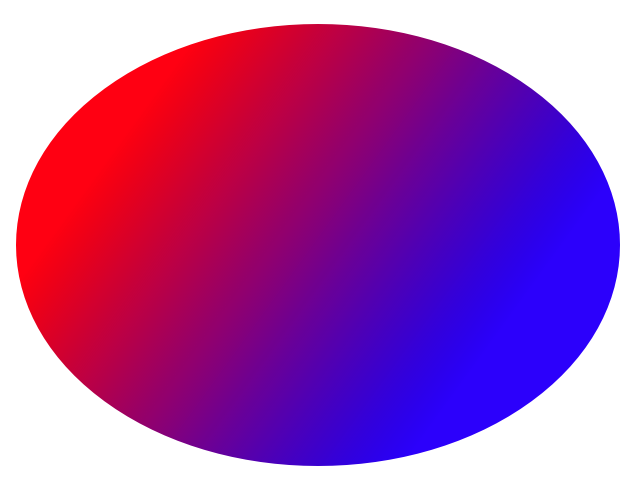
To demonstrate this, here’s a red-blue gradient (shown in Acorn to visualize the gradient image’s own transparency):
If we extract the blue channel, as shown above, we get this:
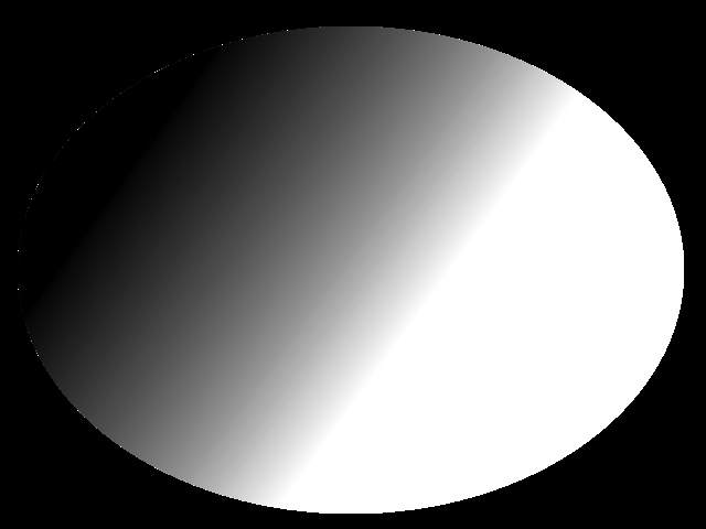
Note how the red parts of the gradient are black, because we extracted the blue channel, and there was little to no blue there.
Likewise, if we extract the red channel, we get this:
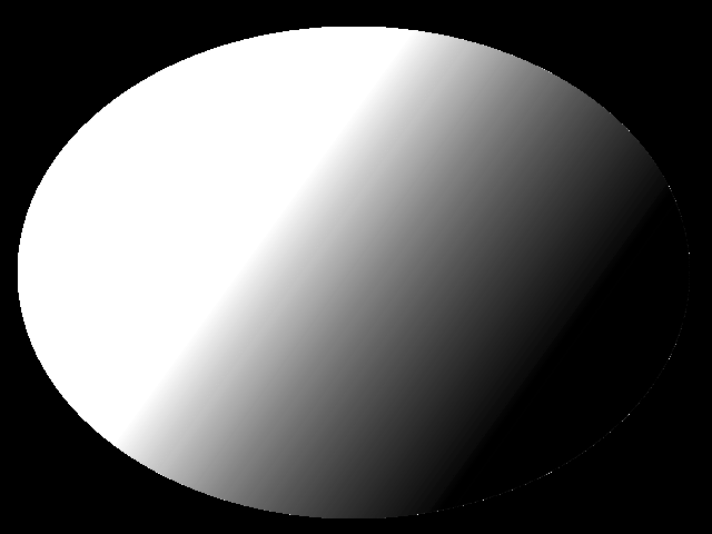
In this case, the converse of the blue-channel mask.
(By the way, in case you’re wondering: No, I don’t know what caused the white pixels along the edge. It could be a Lineform bug, or a Core Image bug, or a graphics-card bug. I didn’t keep the original Lineform file for the source image, stupidly, but in case you’d like to test it on your own machine, I re-created it. Here’s a PDF of the replica; you can use image to convert it to PNG. I can confirm that I saw similar results with this image to the results with the image I used for this post.)
You can even mix up the colors of an image. Suppose we want to reverse that gradient:
- Set the Red Vector to 0, 0, 1, 0. (In other words, replace red with blue.)
- Set the Blue Vector to 1, 0, 0, 0. (In other words, replace blue with red.)
- Leave the Alpha and Bias Vectors at the default values. (In other words, we’re leaving the alpha channel unchanged this time.)
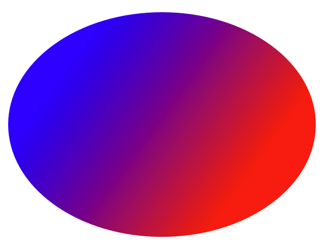
The red-to-blue gradient is now a blue-to-red gradient.
So what is this good for?
Well, mainly, so you can create mask images. Several filters require these, such as the Blend with Mask filter in the Stylize category. The Color Matrix filter makes this easy, although you still have to save the mask image somewhere.
It’s even easier in Opacity, where you can create a Color Matrix filter layer, configure it using the Layer Inspector, then hide it by clicking its eye icon. This way, the filter layer won’t show up in the rendered document (or in any of its build products), but you can still use its result as the mask to another filter layer.


 →
→ 